DIY Localization Sensor Network
Overview
This project aims to use HC-SR04 ultrasonic sensors in conjunction with NU32 boards using PIC32 microcontrollers and XBee radio tranceivers in a sensor network for localization of a mobile robot. The goal is to allow the mobile robot to navigate a simple space in limited sensor circumstances.
The ultrasonic sensors are hooked up and receive a >=5 millisecond pulse of 5V from the PIC32, and then the returned signal is timed for a time of flight distance measurement. This is done by all nodes in the network, and they transmit their measurements in AT mode to a central node. This central node aggregates and processes the distances for trilateration of an object in the network’s measurement area. This object can be a mobile robot enabled with an XBee RF module which receives a measure which it can then minimize toward a known goal location within the network. Instead of using UART3 to send data to a computer, this would require sending data back over UART2 to the XBee radio tranceiver directly to the XBee on the mobile robot.
The project along with a deeper explanation, videos, and a how-to guide on how I built and developed the project (and its ongoing developments) can be viewed here
Background
Requirements
- 4+ NU32 boards with PIC32 microcontrollers (1 per node including central node)
- 3+ HC-SR04 ultrasonic sensors (1 per node)
- 4+ XBee units (one per node including central node)
- Along with this, it is helpful to have a breakout board with header pins for each XBee
- Wire for connecting components (and wire-strippers)
- Soldering equipment
- 4+ breadboards or something with which to connect components
- 1+ XBee development board
HC-SR04 Measurements:
Vertical angle range (measurements taken at about 1 meter distance from the sensor with surface perpendicular to ultrasonic signal): 1 degree below plane of measurement 6.0 degrees above plane of measurement
Horizontal angle range (measurements taken at about 1 meter distance from the sensor with surface perpendicular to ultrasonic signal) 14.5 degrees with 1-2 degrees of variation from side to side
These range measurements are most accurate with orthogonal surfaces and decrease as the angle of the surface to the signal moves away from 90 degrees. However, a range of about 5-10 degrees remains accurate regardless of surface in front of the sensor.
Due to the angular range limitations on these sensors, the ideal setup includes angling multiple sensors in conjunction and fusing the data from them.
Trilateration summary:
Trilateration is related to triangulation but different in that it does not use angles. Instead, it uses distances. These can be thought of as radii of circles around three initial, known points. These are our edge nodes in this project. This architecture can be repeated in many different adjacent or overlapping triangles. Since we have three circles and three distances, we can find the intersection between the three. It is important to consider that there may not be three good measurements, and this will bring to the forefront a flow of measurement possibilities. For now, we will only look at having three good measurements. The known positions are of the nodes at locations (x_i, y_i) for each node with index i.
(-2x1 + 2x2) * x + (-2y1 + 2y2) * y = r12 - r22 - x12 + x22 - y12 + y22
(-2x2 + 2x3) * x + (-2y2 + 2y3) * y = r22 - r32 - x22 + x32 - y22 + y32
⇒
Ax + By = C
Dx + Ey = F
⇒
x = (CE - FB)⁄(EA - BD)
y = (CD - AF)⁄(BD - AE)
Implementation
Sensor Signals
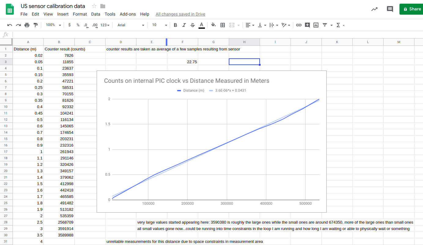
In order to acheive a distance measurement using the HC-SR04 ultrasonic sensors, the sensor must be powered with 5V to VCC, grounded, and receive a high signal pulse for greater than 5 milliseconds. This signal is sent to the trig pin (short for “trigger”) to initialize the sensor’s sending of the ultrasonic pulses. The result is a signal received on the echo pin. The signal is high for the period of time during which a return signal has not been received by the HC-SR04. This must be read and timed by a sensor node, but the length of time the signal is active directly corellates to the time of flight of the sound that leaves the sensor and arrives back at the sensor. So this tells us that the time sensed is 2 times the distance between the sensor and the object detected divided by the speed of sound at the locale in which the sensor is measuring. Here, that is Evanston, IL in winter and spring temperatures and humidity. Gathering data allowed me to tune the sensors from a base estimate of the speed of sound in order to get accurate measurements with signal-orthogonal surfaces within a few centimeters at distances of up to several meters. This tuning method will be required for your own use of the system.
- Find the average speed of sound in your area at the time of year which you would like to use it
- Use this as a starting point and take measurements with known distances
- Edit the distance calculation function to use your own sound constant for calculations
NU32 Communication
All communication can be done over UART. However, since multiple types of communication are necessary for the central node, I have chosen UART2 and UART3. UART3 is used for communication with a host computer for debugging and further processing while UART2 is used for communication with XBee units which I will discuss more below.
Signal pulses can be sent with a buffered digital output. I use pin 51 (D3) for the buffered digital output and D4 to read the response as digital input. I chose these since neither of them conflicted with other needed pins.
For communication with the XBee units, I use UART2, which uses pins F4, F5, B14, and B8 for Data-Out (DOUT), Data-In (DIN), Clear-To-Send (CTS), and Ready-To-Send (RTS). The latter two coordinate hardware flow control between the PIC32 and the XBee unit. The pair must have pins connected to their opposing pairs. Output from the PIC goes to DIN on the XBee. Input to the PIC goes to DOUT on the XBee. CTS on the PIC goes to RTS on the XBee. RTS on the PIC goes to CTS on the XBee.
Using CTS and RTS simplifies the reading and writing to UART. If these are not used and hardware flow-control is not enabled on the PIC and on the XBee, then care must be taken to read the associated UART flags and clear the appropriate buffers. Using hardware flow-control greatly simplifies this communication.
XBee RF Units
XBee RF units send and receive data over radio. They have two operating modes, AT and API. AT mode allows the units to send and receive any data written to UART. API mode enforces a structure of packets. With this enforced structure comes many benefits, however. Direct sending between XBee units depending on address is allowed under this circumstance. Otherwise, the communication casts a wide net when communicating with all other units having a certain range of address. This is controlled by the DL (destination address low) and MY (my 16-bit source address) settings on the XBee. In AT mode, only two sets of addresses can communicate with each other and must have complementary values of MY and DL. (One possessing DL=0, MY=1 and the other possessing DL=1, MY=0 for example). These settings are not exclusive to XBee units and may be reused however, allowing for a many-unit network in AT mode.
XCTU is a software which allows a user to directly read and update settings on the XBee units when they are connected to a computer via a development board.
Baud rate is another important factor in communication between XBees and between an XBee and a computer. The source and sink must be reading the data at the same baud rate, or they will not be able to understand the data. For simplicity, I chose 9600 baud for this project. Higher baud is available.
Beyond baud, the units must be on the same Channel (the CH setting) and have the same PAN ID (the ID setting).
For the purpose of this project, I use the 802.1.5.4 firmware for the XBees. This can be changed through XCTU as well.
Once this is all done, the PIC will be able to read from and write to the XBee.
Design
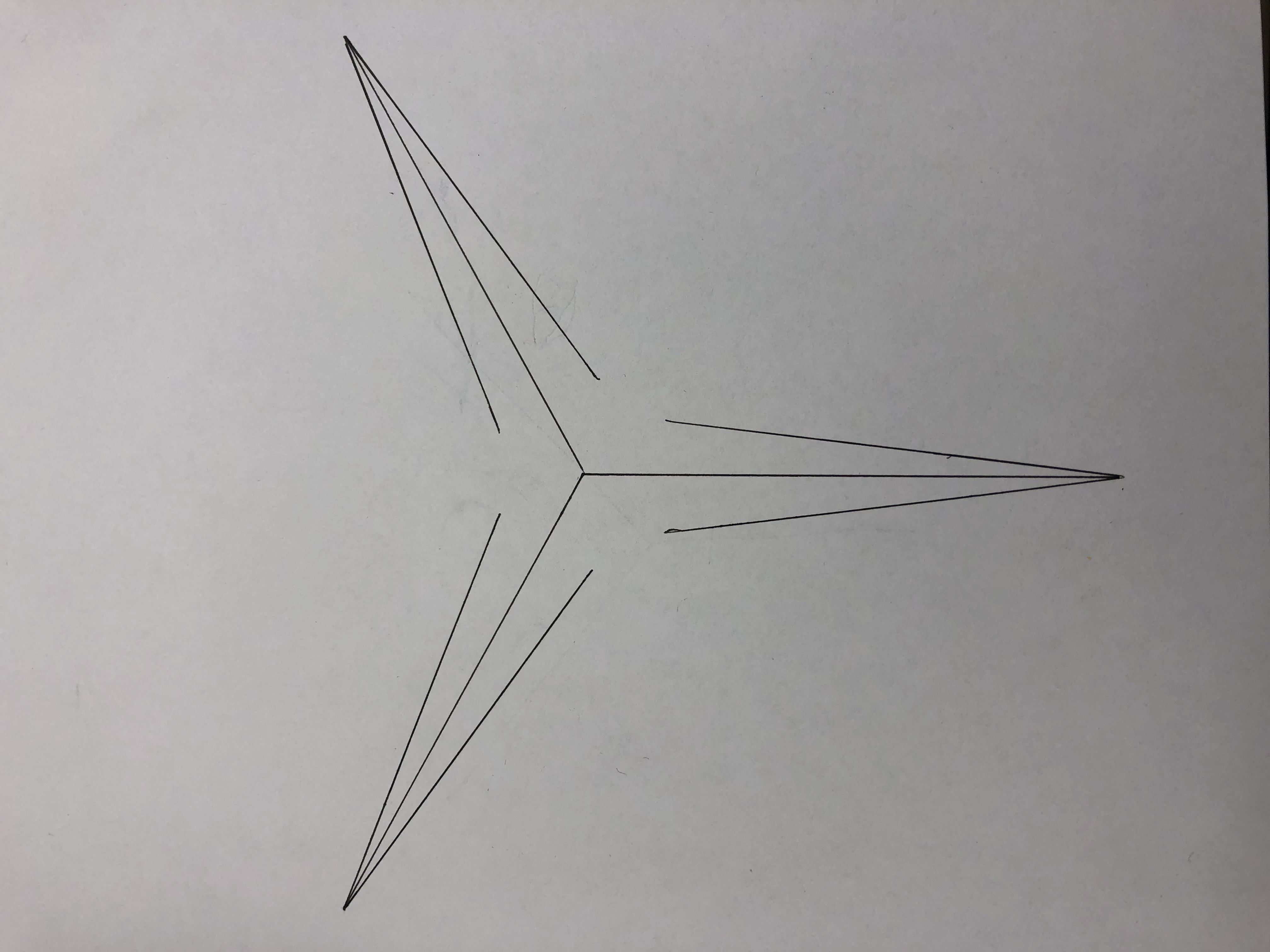
The nodes must be placed such that they can sense an object between them and compute its location relative to them. Using trilateration requires that the minimum is three sensors. Using equilateral triangles for placement of nodes together simplifies the geometry of the ranges. In this project, one sensor is currently used at each node.
Due to the limitations mentioned in the measurement section for the HC-SR04 sensors, this limits the area of full-vision measurement (the space which is visible by all nodes) to the center of the triangle. The effective area of tracking is 4.65% of the area of the triangle. This is quite small unless a large side-length is chosen. I was not able to measure over large side-length setups, so I opted to design a higher area-ratio setup. Adding more sensors in a fanned array gives 19.6% and 48.5% area of the whole triangle for two and three sensors per node respectively. This complicates the data processing but not by much. One more digital input pin per sensor will be required. Then, when any of the sensors on a node sense an object, that distance will be considered dominant. If approximations are used for the parts of the triangular arena which are visible by less than three nodes, then a higher visible area ratio can be acheived.
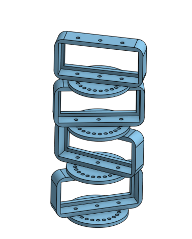
These constraints inform my design of a modular sensor tower which allows for adjustable angles and additional sensors in the tower. The tower is built using a combination of 3D-printed pieces to house the sensors and laser-cut discs for angular stability and measurement.
For simple side-length ratios and diagrams describing the effective areas, refer to the images in the images directory. A circuit diagram for an edge node may also be found there. The central node is the same except without the ultrasonic sensor.
There are three areas which can be sensed:
- All three nodes
- This is in the central arena of full-visibility where all three sensor angle fans intersect.
- Two nodes
- Small areas around the central arena of full-vision
- More data can be extrapolated depending on which sensor has a shorter distance measurement or can be approximated to be along the edge of the central full-vision arena for speed and simplicity.
- One node
- Long path in front of a node pointed toward the center
- This can be approximated as a point on a ring within the entire triangular arena.
- Choosing a point between the node and the center of the triangle is the simplest approximation although a crude one.
File Structure
endNode
This contains endNode.c which is the code that runs on edge nodes which send data to the central node.
centralNode
This contains centralNode.c which is the central aggregator and processor of distance information for a group of 3 nodes.
images
The contents of this directory are diagrams and images of the individual nodes themselves during the development process.
libxbee3
This is an API library for use with the XBee units which will be more heavily leveraged during the transition to using API mode instead of AT mode but which is not currently used.
scripts
This contains a Python prototype for testing connectivity between XBee units on development boards.
xbee_ansic_library
This is currently not used but will be more heavily leveraged during the transition into using API mode instead of AT mode.
docs
This directory contains assorted documents related to the initial development of this project.
trilateration.c
This contains code for trilateration given initial node positions and distances from nodes.
ultrasonic.c
This contains code for interfacing with the ultrasonic sensor and reading data from it.
xbeeInterfacing.c
This is for interfacing with the XBee units via the PIC to read and write relevant settings. Currently, the only use is to read an identification value to assign to the nodes as an address for use in data structuring over RF.
Resources:
- XBee Data sheet: https://www.sparkfun.com/datasheets/Wireless/Zigbee/XBee-Datasheet.pdf
- Notes on trilateration: https://math.stackexchange.com/questions/884807/find-x-location-using-3-known-x-y-location-using-trilateration
Contributing
If contributing to the modifications in our project here, please follow the following steps:
- Fork the repository
- Add your modifications to either the dev branch or a branch off of the dev branch
- Make a pull request with informative descriptions
Ongoing Development
Current work:
- Additional sensor input
- Multiple sets of three nodes
- API mode support
- Distributed computation (no central node)
Author
- Mark Dyehouse -ThePenultimatum
License
This project is licensed under the MIT License - see the LICENSE file for details
Acknowledgments
- Matt Elwin (Northwestern U.)
- Nick Marchuk (Northwestern U.)